3.1. Introduction
In chemical engineering process operations, fluids are typically conveyed through pipelines, in which viscous action—with or without accompanying turbulence—leads to “friction” and a dissipation of useful work into heat. Such friction is normally overcome either by means of the pressure generated by a pump or by the fluid falling under gravity from a higher to a lower elevation. In both instances, it is usually necessary to know what flow rate and velocity can be expected for a given driving force. This topic will now be discussed.
Fig. 3.1 shows a pipe fitted with pressure gauges that record the pressures p1 and p2 at the beginning and end of a test section of length L. A horizontal pipe is intentionally chosen because the observations are not then complicated by the effect of gravity. In addition, for good results, it is desirable that a substantial length of straight pipe should precede the first pressure gauge, in order that the flow pattern is fully developed (no longer varying with distance along the pipe) at that location.
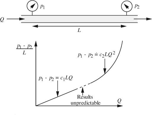
Fig. 3.1 Pressure drop in a horizontal pipe.
Reynolds, Osborne, born 1842 in Belfast, Ireland; died 1912 in Somerset, England. Born into an Anglican clerical family, Reynolds entered an apprenticeship in 1861 with Edward Hayes, a mechanical engineer, before obtaining a degree in mathematics at Cambridge in 1867. After brief employment as a civil engineer, he competed successfully the next year for a newly created professorship at Owens College, Manchester, holding this position for the next 37 years. He worked on a wide range of topics in engineering and physics. He demonstrated the significance of the dimensionless group that now bears his name in his paper, “An experimental investigation of the circumstances which determine whether the motion of water in parallel channels shall be direct or sinuous and of the law of resistance in parallel channels,” Philosophical Transactions of the Royal Society, Vol. 174, pp. 935–982 (1883). His analogy between heat and momentum transport (see Chapter 9) was published in his paper “On the extent and action of the heating of steam boilers,” Proceedings of the Manchester Literary and Philosophical Society, Vol. 14, p. 8 (1874–1875). In 1885, he attributed the name dilatancy to the ability of closely packed granules to increase the volume of their interstices (the void fraction) when disturbed. He was elected a Fellow of the Royal Society in 1877.
Source: Dictionary of Scientific Biography, Charles Scribner’s Sons, New York, 1975.
For a given flow rate, repetition of the experiment for different lengths demonstrates that the pressure drop (p1 – p2) is directly proportional to L. Hence, it is appropriate to plot the pressure drop per unit length (p1 – p2)/L (the negative of the pressure gradient dp/dz, where z denotes distance along the pipe) against the volumetric flow rate Q. There are three distinct flow regimes in the resulting graph:
1. For flow rates that are low (in a sense to be defined shortly), the pressure gradient is directly proportional to the flow rate.
2. For intermediate flow rates, the results are irreproducible, and alternate seemingly randomly between extensions of regimes 1 and 3.
3. For high flow rates, the pressure gradient is closely proportional to the square of the flow rate.
These regimes are known as the laminar, transition, and turbulent zones, respectively. The situation is further illuminated by the famous 1883 experiment of Sir Osborne Reynolds (see box above), similar to that illustrated in Fig. 3.2, where a liquid flows in a transparent tube. A fine steady filament of a dye is introduced by a hypodermic needle into the center of the flowing liquid stream, care being taken to ensure that there is no instability due to an imbalance of velocities. (For gases, the flow can be visualized by injecting a filament of smoke, such as kerosene vapor.) Again, three distinct flow regimes are found, which correspond exactly to those already encountered above:
1. For low flow rates, Fig. 3.2(a), the injected dye jet maintains its integrity as a long filament that travels along with the liquid. (The jet actually broadens gradually, due to diffusion.)
2. For intermediate flow rates, the results are irreproducible, and seem to alternate between extensions of regimes 1 and 3.
3. For high flow rates, Fig. 3.2(b), the jet of dye mixes very rapidly with the surrounding liquid and becomes highly diluted, so that it soon becomes invisible. The reason is that the liquid flow in the pipe is unstable, consisting of random turbulent motions superimposed on the bulk flow to the right.
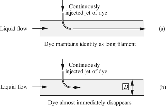
Fig. 3.2 The Reynolds experiment.
Further experiments show that the three regimes do not depend solely on the flow rate, but on a dimensionless combination of the mean fluid velocity um, its density ρ and viscosity μ, and the diameter D of the pipe. The combination or dimensionless group is defined by:
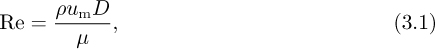
and is called the Reynolds number, and indicates the relative importance of inertial effects (as measured by ![]() —see Eqn. (3.26), for example) to viscous effects (μum/D). Table 3.1 shows which regime can be expected for a given Reynolds number. The exponent on Q is 1.8 or 2, depending on whether the pipe is hydraulically smooth or rough, respectively, in a sense to be defined later. In Sections 3.2 and 3.3 we shall study flow in the laminar and turbulent regimes more closely.
—see Eqn. (3.26), for example) to viscous effects (μum/D). Table 3.1 shows which regime can be expected for a given Reynolds number. The exponent on Q is 1.8 or 2, depending on whether the pipe is hydraulically smooth or rough, respectively, in a sense to be defined later. In Sections 3.2 and 3.3 we shall study flow in the laminar and turbulent regimes more closely.
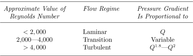
Table 3.1 Dependence of Pipe Flow Regime on the Reynolds Number
3.2. Laminar Flow
In order to avoid the additional complication of gravity (which will be included later), consider flow in the horizontal cylindrical pipe of radius a shown in Fig. 3.3.
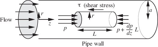
Fig. 3.3 Forces acting on a cylindrical fluid element.
Consider further a moving cylinder of fluid of radius r and length L. In this case, there is zero convective transport of momentum across the two circular ends of the cylinder, and the analysis is simplified.1 Because of the retarding action of the pipe wall, there will be a shear stress τ exerted to the left on the curved surface of the cylinder by the fluid between it and the pipe wall.2 The net pressure force acting on the circular area πr2 of the two ends is exactly counterbalanced by the shear stress acting on the curved surface, of area 2πrL.
Leave a Reply