Many times, reactors are connected in series so that the exit stream of one reactor is the feed stream for another reactor. When this arrangement is used, it is often possible to speed calculations by defining conversion in terms of location at a point downstream rather than with respect to any single reactor. That is, the conversion X is the total number of moles of A that have reacted up to that point per mole of A fed to the first reactor.
Only valid for NO side streams!!
For reactors in series
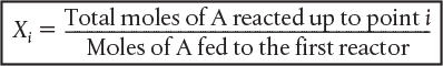

However, this definition can only be used when the feed stream only enters the first reactor in the series and there are no side streams either fed or withdrawn. The molar flow rate of A at point i is equal to the moles of A fed to the first reactor, minus all the moles of A reacted up to point i.
FAi = FA0 – FA0Xi
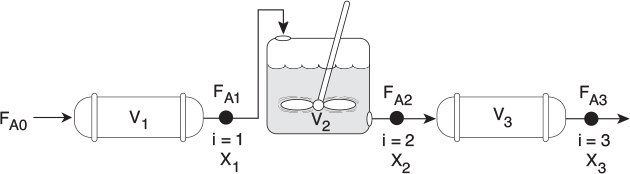
For the reactors shown in Figure 2-3, X1 at point i = 1 is the conversion achieved in the PFR, X2 at point i = 2 is the total conversion achieved at this point in the PFR and the CSTR, and X3 is the total conversion achieved by all three reactors.
To demonstrate these ideas, let us consider three different schemes of reactors in series: two CSTRs, two PFRs, and then a combination of PFRs and CSTRs in series. To size these reactors, we shall use laboratory data that give the reaction rate at different conversions.
2.5.1 CSTRs in Series
The first scheme to be considered is the two CSTRs in series shown in Figure 2-4.
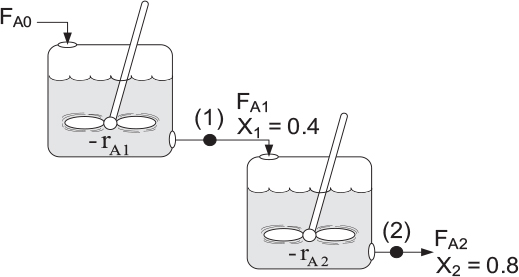
For the first reactor, the rate of disappearance of A is −rA1 at conversion X1.
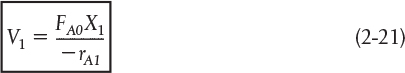
A mole balance on reactor 1 gives
In – Out + Generation = 0
Reactor 1: ![]()
The molar flow rate of A at point 1 is

Combining Equations (2-19) and (2-20), or rearranging
Leave a Reply