Finally, consider the shape of the free surface for the situation shown in Fig. 1.20(a), in which a cylindrical container, partly filled with liquid, is rotated with an angular velocity ω—that is, at N = ω/2π revolutions per unit time. The analysis has applications in fuel tanks of spinning rockets, centrifugal filters, and liquid mirrors.
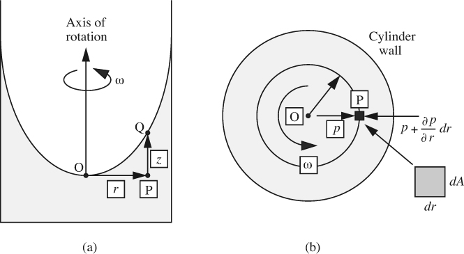
Fig. 1.20 Pressure changes for rotating cylinder: (a) elevation, (b) plan.
Point O denotes the origin, where r = 0 and z = 0. After a sufficiently long time, the rotation of the container will be transmitted by viscous action to the liquid, whose rotation is called a forced vortex. In fact, the liquid spins as if it were a solid body, rotating with a uniform angular velocity ω, so that the velocity in the direction of rotation at a radial location r is given by υθ = rω. It is therefore appropriate to treat the situation similar to the hydrostatic investigations already made.
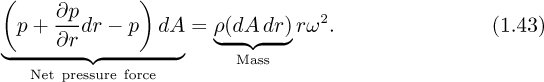
Suppose that the liquid element P is essentially a rectangular box with cross-sectional area dA and radial extent dr. (In reality, the element has slightly tapering sides, but a more elaborate treatment taking this into account will yield identical results to those derived here.) The pressure on the inner face is p, whereas that on the outer face is p + (∂p/∂r)dr. Also, for uniform rotation in a circular path of radius r, the acceleration toward the center O of the circle is rω2. Newton’s second law of motion is then used for equating the net pressure force toward O to the mass of the element times its acceleration:
Note that the use of a partial derivative is essential, since the pressure now varies in both the horizontal (radial) and vertical directions. Simplification yields the variation of pressure in the radial direction:
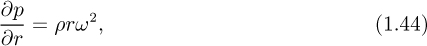
so that pressure increases in the radially outward direction.
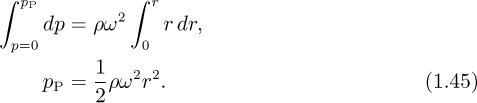
Observe that the gauge pressure at all points on the interface is zero; in particular, pO = pQ = 0. Integrating from points O to P (at constant z):
However, the pressure at P can also be obtained by considering the usual hydro-static increase in traversing the path QP:

Elimination of the intermediate pressure pP between Eqns. (1.45) and (1.46) relates the elevation of the free surface to the radial location:
Thus, the free surface is parabolic in shape; observe also that the density is not a factor, having been canceled from the equations.
There is another type of vortex—the free vortex—that is also important, in cyclone dust collectors and tornadoes, for example, as discussed in Chapters 4 and 7. There, the velocity in the angular direction is given by υθ = c/r, where c is a constant, so that υθ is inversely proportional to the radial position.
Example 1.8—Overflow from a Spinning Container
A cylindrical container of height H and radius a is initially half-filled with a liquid. The cylinder is then spun steadily around its vertical axis Z-Z, as shown in Fig. E1.8. At what value of the angular velocity ω will the liquid just start to spill over the top of the container? If H = 1 ft and a = 0.25 ft, how many rpm (revolutions per minute) would be needed?
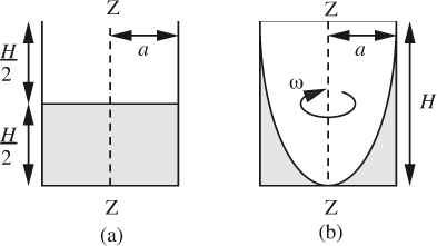
Fig. E1.8 Geometry of a spinning container: (a) at rest, (b) on the point of overflowing.
Solution
From Eqn. (1.47), the shape of the free surface is a parabola. Therefore, the air inside the rotating cylinder forms a paraboloid of revolution, whose volume is known from calculus to be exactly one-half of the volume of the “circumscribing cylinder,” namely, the container.8 Hence, the liquid at the center reaches the bottom of the cylinder just as the liquid at the curved wall reaches the top of the cylinder. In Eqn. (1.47), therefore, set z = H and r = a, giving the required angular velocity:
8 Proof can be accomplished as follows. First, note for the parabolic surface in Fig. E1.8(b), r = a when z = H, so, from Eqn. (1.47), ω2/2g = H/a2. Thus, Eqn. (1.47) can be rewritten as:

The volume of the paraboloid of air within the cylinder is therefore:
which is exactly one-half of the volume of the cylinder, πa2H. Since the container was initially just half filled, the liquid volume still accounts for the remaining half.
For the stated values:


Problems for Chapter 1
1. Units conversion—E. How many cubic feet are there in an acre-foot? How many gallons? How many cubic meters? How many tonnes of water?
2. Units conversion—E. The viscosity μ of an oil is 10 cP and its specific gravity s is 0.8. Reexpress both of these (the latter as density ρ) in both the lbm, ft, s system and in SI units.
3. Units conversion—E. Use conversion factors to express: (a) the gravitational acceleration of 32.174 ft/s2 in SI units, and (b) a pressure of 14.7 lbf/in2 (one atmosphere) in both pascals and bars.
4. Meteorite density—E. The Barringer Crater in Arizona was formed 30,000 years ago by a spherical meteorite of diameter 60 m and mass 106 t (tonnes), traveling at 15 km/s when it hit the ground.9 (Clearly, all figures are estimates.) What was the mean density of the meteorite? What was the predominant material in the meteorite? Why? If one tonne of the explosive TNT is equivalent to five billion joules, how many tonnes of TNT would have had the same impact as the meteorite?
9 Richard A.F. Grieve, “Impact cratering on the earth,” Scientific American, Vol. 262, No. 4, p. 68 (1990).
5. Reynolds number—E. What is the mean velocity um (ft/s) and the Reynolds number Re = ρumD/μ for 35 gpm (gallons per minute) of water flowing in a 1.05-in. I.D. pipe if its density is ρ = 62.3 lbm/ft3 and its viscosity is μ = 1.2 cP? What are the units of the Reynolds number?
6. Pressure in bubble—E. Consider a soap-film bubble of diameter d. If the external air pressure is pa, and the surface tension of the soap film is σ, derive an expression for the pressure pb inside the bubble. Hint: Note that there are two air/liquid interfaces.
7. Reservoir waterflooding—E. Fig. P1.7(a) shows how water is pumped down one well, of depth H, into an oil-bearing stratum, so that the displaced oil then flows up through another well. Fig. P1.7(b) shows an enlargement of an idealized pore, of diameter d, at the water/oil interface.
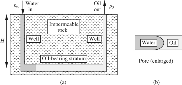
Fig. P1.7 Waterflooding of an oil reservoir.
If the water and oil are just starting to move, what water inlet pressure pw is needed if the oil exit pressure is to be po? Assume that the oil completely wets the pore (not always the case), that the water/oil interfacial tension is σ, and that the densities of the water and oil are ρω and ρo, respectively.10
10 D.L. Katz et al., Handbook of Natural Gas Engineering, McGraw-Hill, New York, 1959, p. 57, indicates a wide range of wettability by water, varying greatly with the particular rock formation.
8. Barometer reading—M. In your house (elevation 950 ft above sea level) you have a barometer that registers inches of mercury. On an average day in January, you telephone the weather station (elevation 700 ft) and are told that the exact pressure there is 0.966 bar. What is the correct reading for your barometer, and to how many psia does this correspond? The specific gravity of mercury is 13.57.
9. Two-layer buoyancy—E. As shown in Fig. P1.9, a layer of an unknown liquid A (immiscible with water) floats on top of a layer of water W in a beaker. A completely submerged cylinder of specific gravity 0.9 adjusts itself so that its axis is vertical and two-thirds of its height projects above the A/W interface and one-third remains below. What is the specific gravity of A? Solve the problem two ways—first using Archimedes’ law, and then using a momentum or force balance.
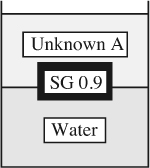
Fig. P1.9 Cylinder immersed in water and liquid A.
10. Differential manometer—E. The U-tube shown in Fig. P1.10 has legs of unequal internal diameters d1 and d2, which are partly filled with immiscible liquids of densities ρ1 and ρ2, respectively, and are open to the atmosphere at the top.
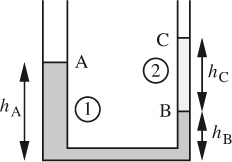
Fig. P1.10 U-tube with immiscible liquids.
If an additional small volume υ2 of the second liquid is added to the right-hand leg, derive an expression—in terms of ρ1, ρ2, υ2, d1, and d2—for δ, the amount by which the level at B will fall. If ρ1 is known, but ρ2 is unknown, could the apparatus be used for determining the density of the second liquid?
Hints: The lengths hA, hB, and hC have been included just to get started; they must not appear in the final result. After adding the second liquid, consider hC to have increased by a length Δ—a quantity that must also eventually be eliminated.
11. Ascending bubble—E. As shown in Fig. P1.11, a hollow vertical cylinder with rigid walls and of height H is closed at both ends, and is filled with an incompressible oil of density ρ. A gauge registers the pressure at the top of the cylinder. When a small bubble of volume υ0 initially adheres to point A at the bottom of the cylinder, the gauge registers a pressure p0. The gas in the bubble is ideal, and has a molecular weight of Mw. The bubble is liberated by tapping on the cylinder and rises to point B at the top. The temperature T is constant throughout. Derive an expression in terms of any or all of the specified variables for the new pressure-gauge reading p1 at the top of the cylinder.
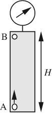
Fig. P1.11 Bubble rising in a closed cylinder.
12. Ship passing through locks—M. A ship of mass M travels uphill through a series of identical rectangular locks, each of equal superficial (bird’s-eye view) area A and elevation change h. The steps involved in moving from one lock to the next (1 to 2, for example) are shown as A–B–C in Fig. P1.12. The lock at the top of the hill is supplied by a source of water. The initial depth in lock 1 is H, and the density of the water is ρ.
(a) Derive an expression for the increase in mass of water in lock 1 for the sequence shown in terms of some or all of the variables M, H, h, A, ρ, and g.
(b) If, after reaching the top of the hill, the ship descends through a similar series of locks to its original elevation, again derive an expression for the mass of water gained by a lock from the lock immediately above it.
(c) Does the mass of water to be supplied depend on the mass of the ship if: (i) it travels only uphill, (ii) it travels uphill, then downhill? Explain your answer.
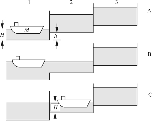
Fig. P1.12 Ship and locks.
13. Furnace stack—E. Air (ρa = 0.08 lbm/ft3) flows through a furnace where it is burned with fuel to produce a hot gas (ρg = 0.05 lbm/ft3) that flows up the stack, as in Fig. P1.13. The pressures in the gas and the immediately surrounding air at the top of the stack at point A are equal.
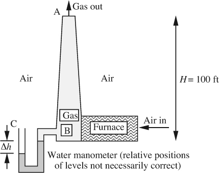
Fig. P1.13 Furnace stack.
What is the difference Δh (in.) in levels of the water in the manometer connected between the base B of the stack and the outside air at point C? Which side rises? Except for the pressure drop across the furnace (which you need not worry about), treat the problem as one in hydrostatics. That is, ignore any frictional effects and kinetic energy changes in the stack. Also, neglect compressibility effects.
14. Hydrometer—E. When a hydrometer floats in water, its cylindrical stem is submerged so that a certain point X on the stem is level with the free surface of the water, as shown in Fig. P1.14. When the hydrometer is placed in another liquid L of specific gravity s, the stem rises so that point X is now a height z above the free surface of L.
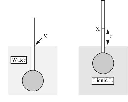
Fig. P1.14 Hydrometer in water and test liquid L.
Derive an equation giving s in terms of z. If needed, the cross-sectional area of the stem is A, and when in water a total volume V (stem plus bulb) is submerged.
15. Three-liquid manometer—E. In the hydrostatic case shown in Fig. P1.15, a = 6 ft and c = 4 ft. The specific gravities of oil, mercury, and water are so = 0.8, sm = 13.6, and sω = 1.0. Pressure variations in the air are negligible. What is the difference b in inches between the mercury levels, and which leg of the manometer has the higher mercury level? Note: In this latter respect, the diagram may or may not be correct.
Leave a Reply